PRODUCT
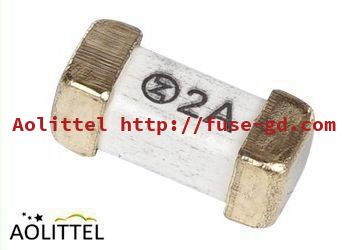

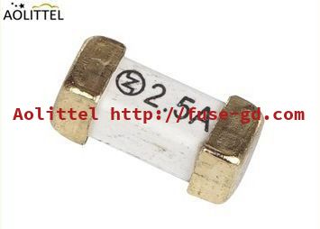
6125 2410 1808 Wire In Air Time Delay Suface Mount Fuse 250V 2A Slow Blow Lead Gold Plated
6125 2410 1808 Wire In Air Time Delay Suface Mount Fuse 250V 2A
Overview
Ao littel surface mount fuses available for addressing a broad range of overcurrent protection applications. Helping to prevent costly damage and promote a safe environment for electronic and electrical equipment, our single-use chip fuses provide performance stability to support applications with current ratings from .5A up to 20A.
______________________________________________________________________________ Download________
Ao littel also offers the telecom FT600 fuse for telecommunications applications. This telecom fuse helps comply with North American overcurrent protection requirements,including Telcordia, GR-1089, TIA-968-A (formerly FCC Part 68), and UL60950 3rd edition
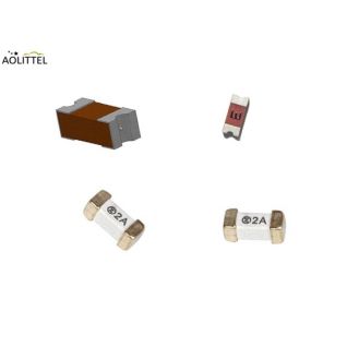
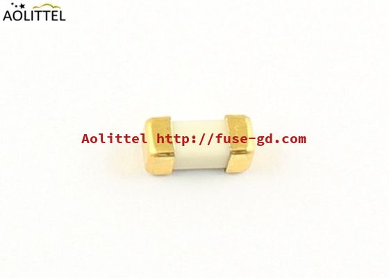
The multi-layer design 2410(6125) is a Wire-In-Air SMD Fuse which is very suitable for secondary level over current protection applications.
Compared our straight wire element design 2410SFV fuses with normal corrugating wire design fuse. The straight wire element in air performs consistent fusing and cutting
characteristics together with excellent inrush current withstanding capability.
Introduced PCB assembly technology into 2410 fuses design and manufacture, we achieved on lead free completely and no end cap falling off risk comparing with traditional ceramic body with end cap fuse.
| Ao littel Surface Mount Fuse Family Member | ||||
| No. | Size | Blow | Voltage | Seires |
| 1 | 0603 | Fast Blow | 32V | 06.000 |
| 2 | 0603 | Time Delay | 32V | 06.100 |
| 3 | 1206 | Fast Blow | 32V | 12.000 |
| 4 | 1206 | Time Delay | 32V | 12.100 |
| 5 | 6125 | Time Delay | 250V | SET |
| 6 | 6125 | Fast Blow | 250V | SEF |
| 7 | 2410 | Fast Blow | 125V | SFE |
| 8 | 2410 | Time Delay | 125V | STE |
| 9 | 1808 | Fast Blow | 300V | SSF |
| 10 | 1808 | Time Delay | 300V | SST |
| 9 | 1032 | Time Delay | 125V | R1032 |
| 10 | 1032 | Fast Blow | 125V | R1032 |
Specification
| Part No. | Ampere Rating | Voltage Rating | Breaking Capacity | Nominal Cold Resistance (Ohms) | I2TMelting Integral(A2.S) | Agency Approvals | |
| UL | CUL | ||||||
| SET0200 | 200mA | 250VAC | 50A@300VAC 50A@250VAC 200A@125VAC | 0.92 | 0.125 | ● | ● |
| SET0250 | 250mA | 0.86 | 0.145 | ● | ● | ||
| SET0300 | 300mA | 0.62 | 0.162 | ● | ● | ||
| SET0315 | 315mA | 0.55 | 0.189 | ● | ● | ||
| SET0375 | 375mA | 0.47 | 0.2 | ● | ● | ||
| SET0400 | 400mA | 0.38 | 0.238 | ● | ● | ||
| SET0500 | 500mA | 0.32 | 0.275 | ● | ● | ||
| SET0600 | 600mA | 0.285 | 0.47 | ● | ● | ||
| SET0630 | 630mA | 0.256 | 0.566 | ● | ● | ||
| SET0700 | 700mA | 0.208 | 0.805 | ● | ● | ||
| SET0750 | 750mA | 0.175 | 1.24 | ● | ● | ||
| SET0800 | 800mA | 0.155 | 1.88 | ● | ● | ||
| SET1100 | 1A | 0.148 | 3.5 | ● | ● | ||
| SET1125 | 1.25A | 0.102 | 4.76 | ● | ● | ||
| SET1150 | 1.5A | 0.085 | 6.305 | ● | ● | ||
| SET1160 | 1.6A | 0.075 | 6.505 | ● | ● | ||
| SET1200 | 2A | 0.044 | 8.95 | ● | ● | ||
| SET1250 | 2.5A | 0.043 | 16.025 | ● | ● | ||
| SET1300 | 3A | 0.033 | 21.56 | ● | ● | ||
| SET1315 | 3.15A | 0.029 | 22.75 | ● | ● | ||
| SET1350 | 3.5A | 0.027 | 27.05 | ● | ● | ||
| SET1400 | 4A | 0.025 | 31.808 | ● | ● | ||
| SET1500 | 5A | 0.019 | 40.25 | ● | ● | ||
| SET1600 | 6A | 0.018 | 67.245 | ● | ● | ||
| SET1630 | 6.3A | 0.017 | 73.55 | ● | ● | ||
| SET1700 | 7A | 0.015 | 76.28 | ● | ● | ||
| SET1800 | 8A | 80.75 | ○ | ○ | |||
| SET2100 | 10A | 0.014 | 110.38 | ○ | ○ | ||
| SET2120 | 12A | 0.013 | 158.08 | ○ | ○ | ||
| SET2150 | 15A | 0.012 | 160.68 | ○ | ○ | ||
| SET2200 | 20A | 166.58 | ○ | ○ | |||
| SET2300 | 30A | 0.011 | 170.56 | ○ | ○ | ||
- These part no. cold resistance and I2t value are pending due to fuse elements shall be customized;
- DC Cold Resistance are measured at <10% of rated current in ambient temperature of 25℃;
- Typical Pre-arching I2t are calculated at 10*In Current or 8ms;
- Min Interrupting Rating: 1.35*In.
Product Characteristics
|
NO. |
Item |
Content |
Reference standards |
| 1 |
Product Marking |
Brand, Ampere Rating | Ao littel marking standards |
| 2 |
Operating Temperature |
-55°C to 125°C | IEC60068-2-1/2 |
| 3 |
Solderability |
T=240°C±5°C , t=3sec±0.5sec, Coverage≥95% | MIL-STD-202, Method 208 |
| 4 |
Resistance to Soldering Heat |
10 sec at 260°C | MIL-STD-202, Method 210, Test condition B |
| 5 |
Insulation Resistance (after Opening) |
10,000 ohms minimum | MIL-STD-202, Method 302, Test Condition A |
| 6 |
Thermal Shock |
5 cycles, -65°C / +125°C, 15 minutes at each extreme | MIL-STD-202, Method 107, Test Condition B |
| 7 |
Mechanical Shock |
100G’s peak for 6 milliseconds, 3cycles | MIL-STD-202, Method 213, Test I |
| 8 |
Vibration |
0.03”amplitude, 10-55 Hz in 1 min. 2hrs each XYZ=6hrs | MIL-STD-202, Method 201 |
| 9 |
Moisture Resistance |
10 cycles | MIL-STD-202, Method 106 |
| 10 |
Salt Spray |
5% salt solution, 48hrs | MIL-STD-202, Method 101, Test Condition B |
Fusing Characteristics
| % of Ampere Rating(In) | Fusing Time |
| 100% * In | 4 hours Min. |
| 200% * In | 120 sec Max. |
| 1000% * In | 10ms Min . |
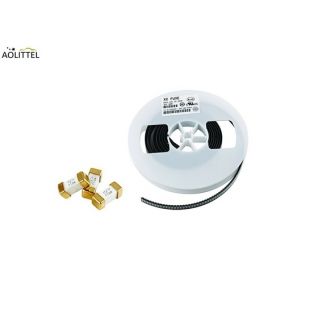
Packaging
Tape in reel ; 1,000 pcs in 7 inches dia. reel, 12mm wide tape, EIA Standard 481
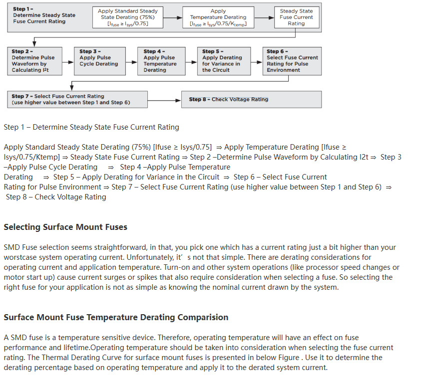
Surface Mount Fuse Selection Flowchart
However, the basic considerations for fuse selection are shown in the flowchart presented in Figure 6. Following this flow chart
will help you select a fuse best suited for your application conditions.